|
4.2.1
|
Main cage rotation speed range
|
40r/min
|
|
4.2.2
|
Max single diameter
|
50mm
|
|
4.2.3
|
Adapt bobbin size
|
PN1400
(φ1400xφ80x1060mm)
|
|
4.2.4
|
Max load capacity
|
3T
|
|
4.2.5
|
Main motor power
|
55KW (AC)
|
|
4.2.6
|
Laying pitch
|
90-1270mm (stepless adjustable)
|
|
4.2.7
|
Cage structure
|
3+3 one cage
|
|
4.2.8
|
Control mode: the winch cage is
operated through the color touch screen of man-machine operation interface,
and the PLC is used to coordinate and control the operation of the winch
cage: start, stop, inching, forward stranding, reverse stranding and other
operations, which match the operation status of the whole machine. Various
operating states can be displayed and controlled on the screen, and the
overall operation is convenient
|
|
4.2.9
|
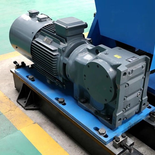
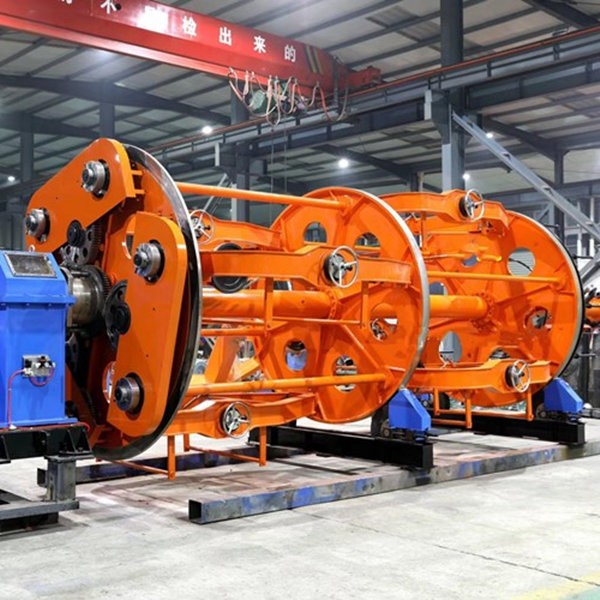
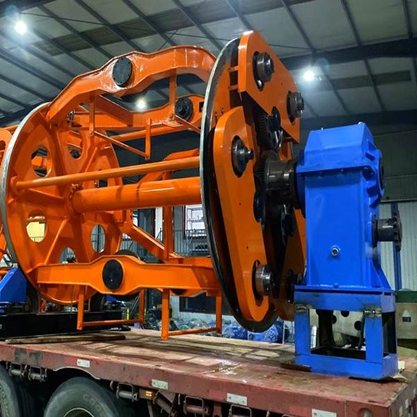
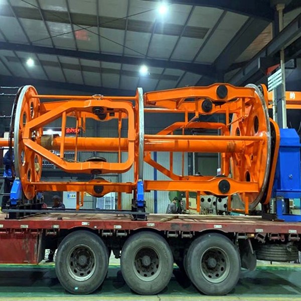
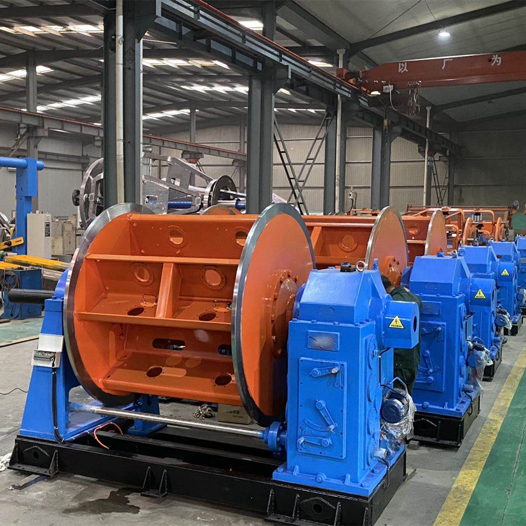
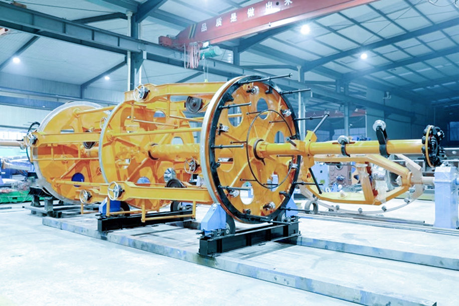
Structure composition: the main
winch cage is 3 + 3 parallel structure, that is, the winch cage is arranged
in two gears, and the cradle is arranged in 3 equal parts in the
circumference of each gear. It is composed of drive motor, reducer, main
shaft, support plate, pay off frame, planetary gear untwisting device, filling
device, brake device, tugboat and base.
|
|
4.2.10
|
Driving mode: the main cage is
driven independently by 55kW variable frequency adjustable speed motor, and
the encoder feedback runs in the closed-loop control system of the whole
machine. The winch cage is loaded and operated by reducer and tugboat group.
The motor and reducer are connected by large sprocket coupling. Compared with
the traditional toothed belt transmission structure, this structure has high
strength and easy maintenance. The gearbox is equipped with large double row
roller self-aligning bearing to support the winch cage, and the gear bearing
inside the box is sprayed and lubricated by the oil pump motor; the winch
cage is supported by two tugboat groups, which are placed on the processing
track, and the position of the tugboat can be adjusted through the screw rod.
The tugboat is made of high polymer nylon material, which has excellent wear
resistance and shock absorption effect.
|
|
4.2.11
|
cradle structure: the cradle frame
is made of CNC laser cutting and welding, and processed by large machine tool
after aging treatment in annealing furnace, with high overall rigidity and
high operation precision. Each basket is equipped with cable tray bracket to
provide protection for the wire materials in the coil
|
|
4.2.12
|
Loading bobbin mode: the end shaft
type manual clamping reel is adopted for the setting out frame in the winch
cage, and the mechanical locking mechanism is provided to prevent the wire
reel from being thrown out. The wire reel is put into the cradle through the
lifting device in the workshop
|
|
4.2.13
|
Tension form: the tension of the
reel in the pay off frame is provided by belt type mechanical friction, and
the tension can be adjusted manually
|
|
4.2.14
|
Back twisting structure: the main winch
cage adopts planetary gear untwisting structure to realize 100% wire
untwisting. All the untwisted gears are carburized and have high wear
resistance
|
|
4.2.15
|
Brake system: the plane air brake
is used to provide braking for the main engine. The whole braking process is
completed through the overall coordinated control of the motor frequency
converter, air brake system and braking resistance by PLC, so as to ensure
the synchronization with the whole machine and the braking efficiency
|
|
4.2.16
|
The front end of the main engine is
equipped with 12 groups of filling frames
|
|
4.2.17
|
The main machine wire distribution
board is equipped with nylon cable sleeve, and the inner diameter of the
sleeve is Ф 50mm
|
|
4.2.18
|
Safety protection device: the hinge
cage is a fixed wall type safety protection net made of porous plate
|
 Ningbo Capstian Technology Co.,Ltd.

